Funkmess(ortungs)geräte
im Bereich Cuxhaven
During the Second World War, various radio detection devices from a wide range of military branches were used here in Cuxhaven, primarily to locate approaching enemy aircraft in good time. Since radar technology was nowhere near as advanced as it is today, different models were sometimes linked together. Prototypes were also tested here in some places.
| Type | Name/Tarnname | Location | Unit | Order / Order | Furnishing |
|---|---|---|---|---|---|
| FlaBttr | Altenbruch | 7./MFlaA 214 | Fire control | 1 x FuMO 213 | |
| FlaBttr | FORT KUGELBAKE | Cuxhaven - Doese | 1./MFlaA 214 | Fire control | 1 x FuMO 22, 1 x FuMO 201 |
| FlaBttr | Urge | Cuxhaven Süderwisch | 1./MFlaA 214 | Fire control | 1 x FuMO 22, 1 x FuMO 201 |
| Smoke | Scharhörn Island | Naval tactical radio location | |||
| FuMG | 1 x FMG 38 G (fB) (DeTe I, A1 device) | ||||
| FlaBttr | Duhner Heide | Fire control | 1 x FuMO 22, 1 x FuMO 201 | ||
| FuSAn | Altenwalde-Pferdemoor | Marine direction finding station | 1 x LW 4 H 3000 / 1943, 1 x KW 4 U 80 | ||
| FlaBttr | Shantung-Pollux | Groden-Neufeld | 2./MFlaA 214 | Fire control | 1 x FuMO 213 |
| SME | By Stosch | Neuwerk Island | 4. DON'T | ||
| FuMG | Berensch | 21./sFlight Reporting Command IV./LnRgt 202 | Radio measuring position 1st order | 1 x FuSE 65 Würzburg-Riese 1 x FuSE 80 Freya A/N 1 x FuSE Freya Wismar | |
| FuSAn | Berensch | Radio position |
Source: http://www.deutschesatlantikwallarchiv.de/radar/germany/rd_.htm Private
By the end of the First World War it had become clear that combating aircraft that were flying ever higher and faster required suitable methods of deploying anti-aircraft artillery. Determining the lead point, which is determined from the direction of movement and speed of the aerial target and the flight time of the projectiles, was proving increasingly problematic. Using the ring sight commonly used for anti-aircraft weapons, the lead point could only be estimated, not determined. The idea of being able to calculate the lead point using the target coordinates of the aerial target and their rate of change led to the development of the first command devices for controlling anti-aircraft batteries. These devices, designed as analog computers, could use the target coordinates determined by optical rangefinders to determine the guide values for the guns and, for large-caliber anti-aircraft weapons, the running time of the time fuse on the grenades. From the beginning of the 1940s these command devices were also coupled to radar stations to determine the target coordinates.
(Example) Command device and its use in an anti-aircraft position
A command device 40 with attached 4-m rangefinder for optical target acquisition and lead point calculationSource: DSC/WW2

Anordnung der einzelnen Komponenten in einer Flakbatterie.
Quelle: Fliegerrevue 15/S5
Which: DSC/WW2
During the day, the target was optically detected and tracked using the 4 m spatial image rangefinder. These values were automatically entered into the command computer. This calculated the lead values for the target point for the measured point of the targeted aircraft in accordance with the "anti-aircraft gunnery gauge" using integral equations and cam disks suitable for the ballistics of the gun. These values were transmitted electrically by cable to a distribution box in the gun position. From there, the values were transmitted in a star shape to the four guns of the anti-aircraft battery with their respective azimuth, elevation and detonator setting devices. The gunners cranked the guns by hand until they were covered by the electrical command device. Four guns (or 8, 12, 16 in a cascade) were always aimed synchronously at a single measured aircraft. The command device was either set up in the center or some distance from the gun position.
When it was cloudy or at night, altitude, direction and speed were initially transmitted by radio measuring devices (FuMG Bsp "Würzburg") to the command device by telephone, later automatically and thus electrically by the conversion device to the Kdo.Ger.40. The guns were aligned as described above.The Kommandogerät 40 was developed in the Zeiss-Ikon AG factory in Dresden, and its first examples appeared as early as 1937, but the device was used on a larger scale from 1941. The Kdo.Ger.40 staff consisted of five people.Source: Wikiwand 8.8 Flak
Small command device C5 (Kleinkog)
Dreiwag coast heavy
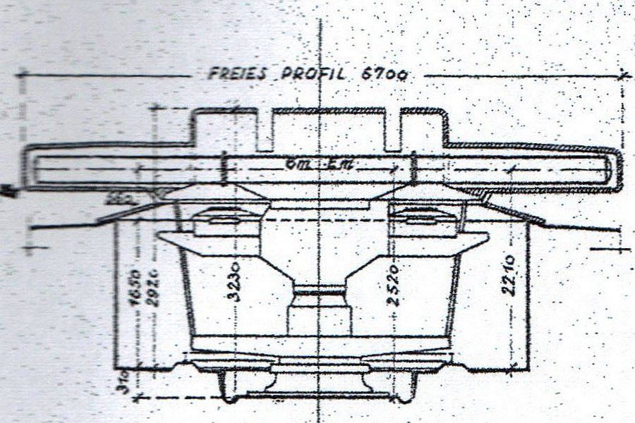
The Dreiwag (three-roller device) is a measuring and command device for heavy anti-aircraft batteries on land and was designed exclusively for the needs of the Navy. It is also equipped with a 6 m optic (EM-6mR(H) spatial imaging rangefinder). The lead angle is determined mechanically by evaluating the angle of impact and the angle of elevation of moving air targets. In principle, it works according to the linear calculation method by means of a scaled, geometric simulation of the aircraft movement in polar coordinates.
A point in space, the target, is determined by the three measurement values: - distance to the measuring point - azimuth angle to the measuring point - elevation angle to the measuring point in relation to a fixed position line on the map plane. The corresponding values are normally determined using the above-mentioned mounted spatial image rangefinder and the associated telescopes and are continuously fed into the command device. Alternatively, they can also be determined and transmitted by a radio measuring device.
Mit diesen Werten wurde die Horizontaltgeschwindigkeit und die Flugrichtung des Zieles ermittelt,
Ein Geschütz, daß das Flugziel bekämpfen soll, darf nicht auf den augenblicklichen Meßpunkt gerichtet sein, sondern auf einen vorausliegenden Punkt des Zielweges, den Treffpunkt. Dieser Punkt ist abhängig von der Ladeverzugszeit und der Flugzeit des Geschosses sowie der Wegstrecke, die das Ziel in dieser Zeit zurücklegt. Der Treffpunkt wird im Kommandogerät errechnet.
Die für die einzelnen Geschütze benötigten Werte werden aus dem Treffpunkt, dem horizontalen und vertikalen Stellungsunterschied sowie der Flugbahn des Geschosses, abhängig von dem Geschoßgewicht, dem Drall, der Pulvertemperatur, der Anfangsgeschwindigkeit, dem Windeinfluss und dem spezifischen Gewicht der Luft, ermittelt.
Weiterhin wird mit den aufgenommenen Werten die Stellzeit für die Zeitzünder der Granaten ermittelt (Flugzeit der Geschosse zum Zielpunkt). Die ermittelten Werte des Dreiwag werden durch die drei Geber an die Empfangssysteme der Geschütze geleitet. Durch den Verteilerkasten ist es möglich, mehrere Geschütze anschließen. Das Gerät selbst muß im Zentrum der Batterie liegen. Es ist transportfähig, dies erfordert aber größere Vorbereitungen. Zudem ist für jegliche Flakbatterie verwendbar und muss nur auf das jeweilige Kaliber eingestellt werden. Zum Schutz der Besatzung ist das Gerät mit einer Panzerkuppel versehen und um 360 Grad drehbar.
The "Dreiwag Küste schwer" with the 6m-R(H) base on the control station 1 of the Flak battery Kugelbake.
Source: Marine helper in the Kugelbake/H..Schönemann battery, Koblenz Military Technology Study Collection
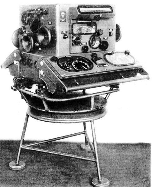
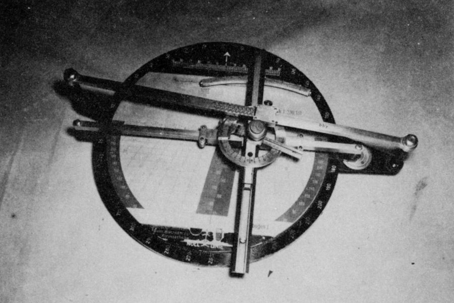
The Flak Windscreen
The anti-aircraft windscreen is used to determine the wind T.-V., the wind lead and the spin depending on distance, aiming direction to the wind direction, wind strength and ballistics. It consists of the following parts: housing, table, cam disc, firing direction indicator, degree ring, glass cover and night lighting system.
The cam disc is placed on the table so that the recess in the latter engages with the pin on the table. There are yellow concentric circles on the cam disc which are used to determine the spin. They become narrower towards the outside as the spin deviation increases with increasing distance. There are also red and green solid lines for determining the wind T.-V. The target height and wind speed can be read in the middle part of the cam disc. The wind direction arrow is also attached here. There are anti-aircraft wind discs from 4 to 34 m/sec., divided from 2 to 2 m/sec. The ballistics are indicated on the edge of the disc. The degree ring is divided into 360 degrees. It is mounted so that it can rotate. The firing direction arrow circles above the cam disc. It is provided with a hm division from 10 to 75 hm.
Nachdem die Nr.9 die Messentfernung ausgerufen hat, greift der Bedienungsmann der Flakwindscheibe dieselbe am Schussrichtungszeiger ab und beobachtet, wo dieser mit einer der Kurven schneidet. Die Werte für Windvorhalt und Drall stellt er an der dreifachen Verbesserung ein. Die Wind-T.-V. ruft er Nr.4 zum Einstellen an der T.-V.-Skala zu. Dabei werden diese Werte genauso verrechnet wie die Kommandoverbesserungen des Flak- Leiters.
Rangefinder 4 m R(H) 36 / German Empire
The spatial image rangefinder with a moving mark was used to determine the distance or height of a target, particularly with the heavy weapons of anti-aircraft artillery. With a simple switching process, it can be switched from a rangefinder to an altimeter and vice versa at any height position.
Measuring principleMeasuring range:Measuring base: Magnification:
Spatial image hiking mark
0.62 bus 50 km4 m
24- and 12-fold
Entrance pupil:
Exit pupil:
Field of view:
40 mm
at 24x 1.7 mm
at 12x 3.4 mmat 24x 29 m at 1000 mat 12x 35 m at 1000 m
Eyepiece adjustment range:
Pupillary distance adjustment range:
Year of introduction:
Lot:
Manufacturer:
Special feature:
Inventory number:
6 can
54 bis 76 mm1936175 kg
Fa. Carl Zeiss, Jena
also called stereo altimeter.22868
The device includes the BGR 36 correction device, 2 10 x 45 directional telescopes (side and elevation), view inclined to the direction of the target by 80°, electric measuring mark illumination, a double observation telescope 10 x 45 and 2 finder telescopes 6 x 30.
Here you can clearly see the double aiming glasses on the Em 4m R40. The container for the four lead collectors 2B38 hangs on the frame. When connected in series, they had a voltage of 4 volts and an output of '76 ampere hours.

Ein Raumbild - Entfernungmessgerät 6 m - R(M), wie es auf dem Dreiwag der Marine verwendet wurde.
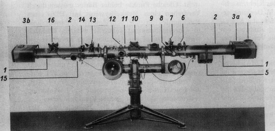
A rangefinder 4m R(H) 34 and 36, viewing side(1) outer tube(2) radiation protection(3a, 3b) right and left base head(4) protective cover for the pendulum altimeter on the side,(5) eyepiece protective cover(6) removable finderscope (right)(7) removable, single-lens directional telescope (right)(8) distance correction(9) measuring wheel(10) viewing to Em(11) coarse sight(12) height correction(13) removable, single-lens directional telescope (left)(14) removable finderscope (left)(15) switch from "Em" to "Hm"(16) removable double observation telescope. (According to 2. Dv. T. 1300)
Source: Military Technology Study Collection Koblenz, Weapons Arsenal S-21
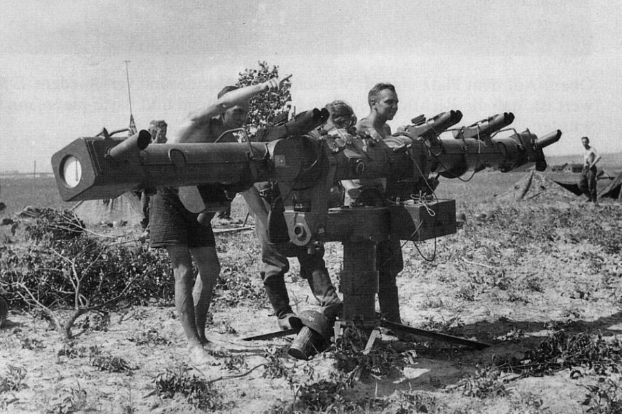
FUSE 62 A Würzburg radar device (FUMO 22 - naval designation)
Radio measuring device was the term used by the German Wehrmacht before and during the Second World War for radio technology systems and devices that were used to locate aircraft or ships, to control the fire of anti-aircraft and coastal artillery, or to guide their own fighter aircraft.
These can be divided into active radio measuring devices (now radar devices) with transmitting and receiving parts, later also called radio measuring device (FuMO), and passive devices that only received signals and did not transmit them.
The official name of the active devices was FuSE (radio transmitting and receiving device). The fire control radar systems of the coastal artillery and naval anti-aircraft guns operated by the Navy were called FuMO (radio measuring and locating device, e.g. FuMO 22). The FuMG 62 "Würzburg" was initially also called FMG 39 (flak measuring device, introduced in 1939).
The FuMG 62 was one of the first pulse radar devices to work with decimeter waves at a frequency of 560 MHz (wavelength 53.6 cm) to accurately determine the distance and altitude of enemy aircraft. Development began in the late 1930s; the first devices were used in 1940. In total, more than 4,000 devices of various model series were probably produced. It was named after the city of Würzburg because the head of Telefunken radar development, Wilhelm Runge, preferred cities as code names.
Those: http://www.atlantikwall.info/radar/technik/flakziel.htm

SMOKING 22
Source: Federal Archives Image 101I-356-1845-08

FUMO 22Source: Federal Archives Image 101I-621-2930-32
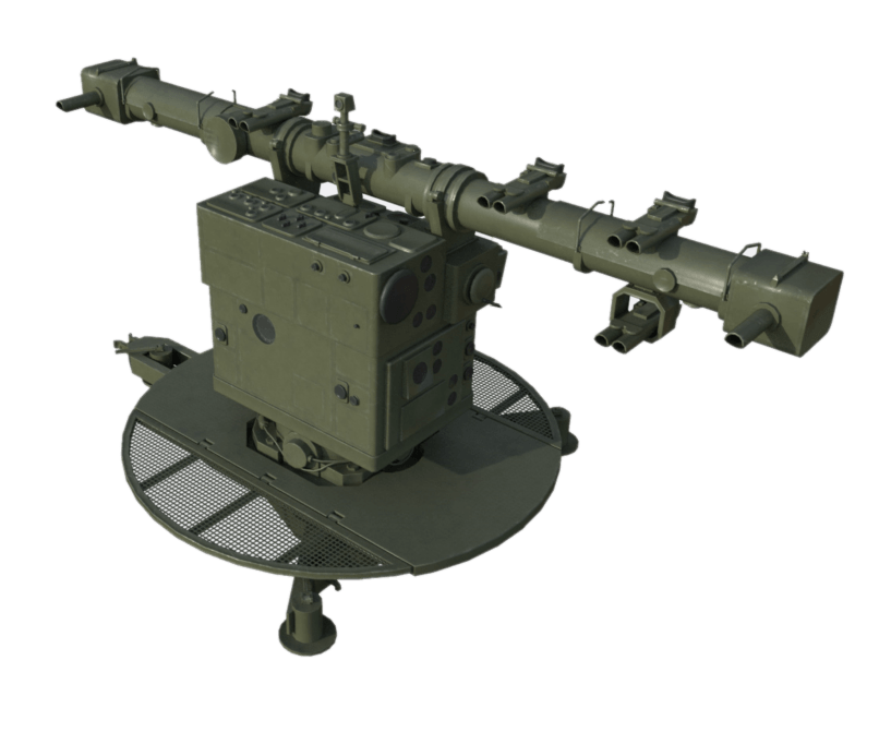
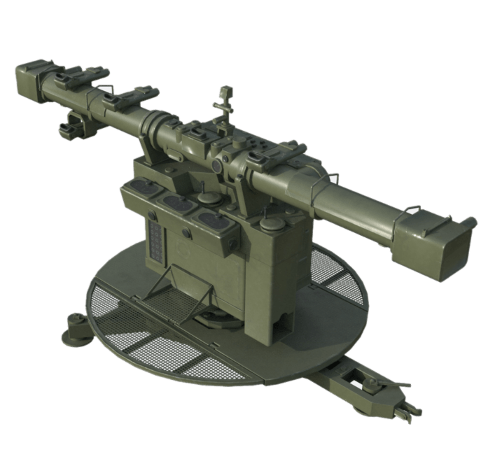
Flakleitgerät 41g (FUMO 201/202 Marinebezeichnung)
Das FuMO 202 Flakleitgerät sendete in der Frequenz 368 MHz mit einer Reichweite zwischen 20 und 30 km. Die deutschen Radarsysteme waren bereits damals in der Lage, seitlich eine Richtung zum Ziel finden. Um allerdings Flugzeuge als echtes Flakradar bekämpfen zu können, wurden jedoch mehr Daten benötigt. Die Antwort der Zeit ist dieses Radargerät das auch in der Lage war, eine Höhenrichtung für eine Messung in der Luft auf elektronischem Wege in Kombination mit dem Entfernungsmesser zu ermitteln. Eines der ersten echten Flak Radarsysteme. Jeder Reflektor hatte seine Aufgabe, die Vertikale war für die Höhenrichtung und die Horizontale für die Seitenrichtung zuständig. Die Anlagen waren in den Flakbatterien in entsprechenden Bettungen oder auf sogenannten Flakleittürmen gelagert.

Those: www.gyges.dk

Quelle: 3dwarehouse.com
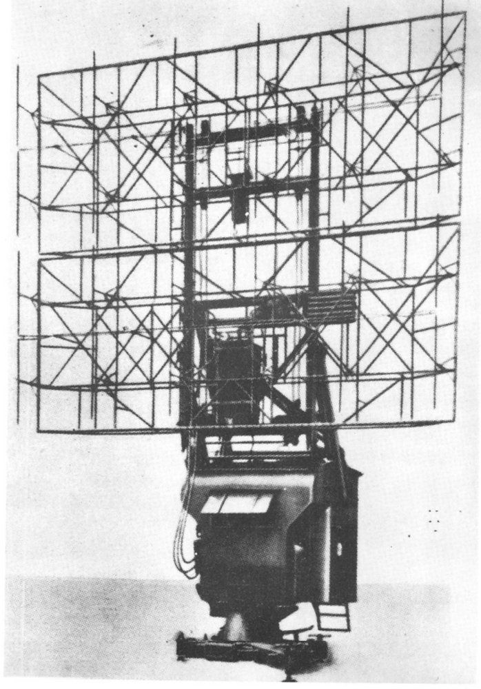
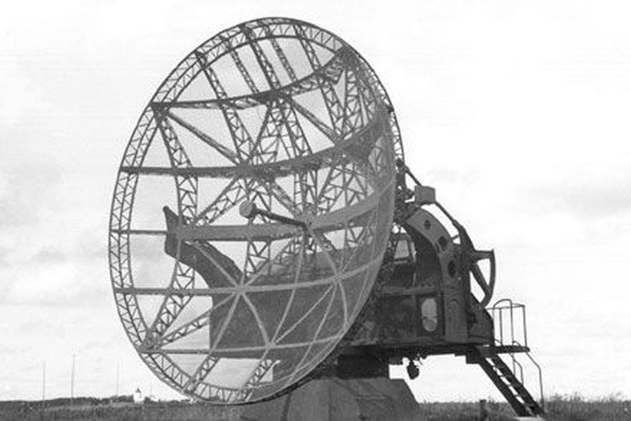
FuMG 65/FuSE 65 Würzburg - Riese (Giant) / German Air Force
The FuMG 65 Würzburg - Riese was a further development of the FuMG 62, which was developed and produced by the Telefunken company. The stationary "giants" (designation: radio transceiver FuSE 65 or radio measuring device FuMG 65), introduced in mid-1941, were used to guide the Luftwaffe's night fighters and were installed on the control towers of the large anti-aircraft towers for fire control. The Luftwaffe expert and general Josef Kammhuber, commander of the night fighters, planned and built a defense line of so-called "canopy bed" positions, which became known to the English under the name of its organizer as the "Kammhuber Line". The line, which was ultimately over 1000 km long, stretched from Denmark to northern France and was a sophisticated system of radio measuring positions, night fighter airfields, anti-aircraft batteries and flight guards, all of which were connected by telephone to fighter control centers. The radar stations with overlapping detection ranges, searchlight positions and night fighter units ready to take off were intended to keep British and later American aircraft away from German airspace. From July 1943, the Allies disrupted the effectiveness of the radar systems by dropping tinfoil strips (chaff). The many radio echoes initially irritated the German air defenses. However, it was soon possible to use the Doppler effect to determine the speed of the detected objects and to block out the slowly floating metal strips. This process made it possible to separate the chaff from the fast-flying aircraft echoes and make them visible again. As the FuMG 65 Würzburg-Riese itself was not able to roughly locate approaching aircraft, it was usually operated in combination with a FuMG 80 Freya. The Freya device was either at a certain distance or it was mounted on the right and left sides of the Würzburg-Riese.
- Search area: 360 degreesRange: Search: 60–80 km, bearing: 50–60 kmTransmission frequency: 560 MHzWeight 15 tonsCrew 6Height 10.20 m / width 4.30 m / length 7.60 mMirror diameter 7.40 m
Quelle: Waffenarsenal 132 , Wikipedia FuSe 65
Private: Denmark
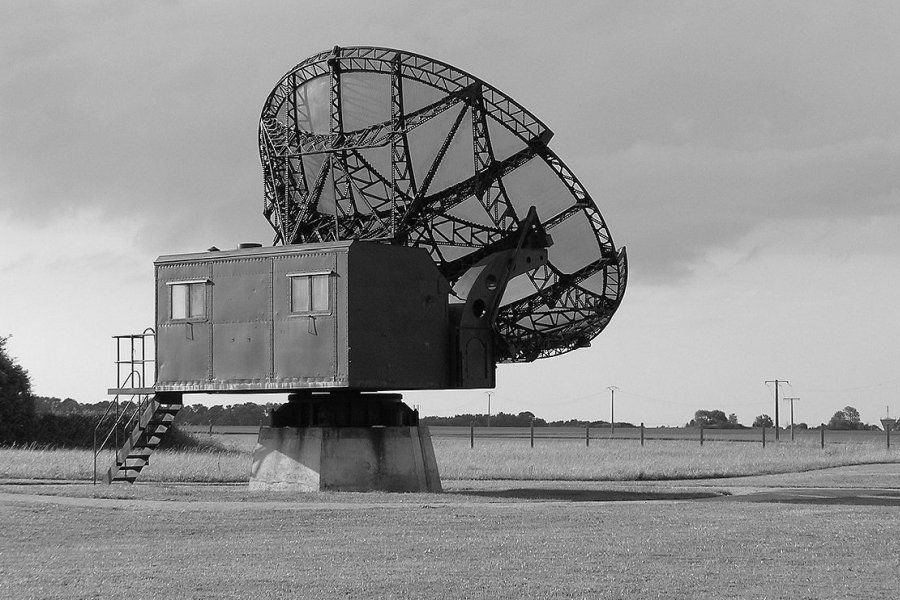
Private: France-Normandy
FuMG 80 Freya - System / German Air Force
The Freya radio measuring device was an early development of radar technology in the German Reich. The code name comes from the Nordic goddess Freya, who is said to have the ability to see at night. In 1940, guiding a night fighter aircraft using ground radar was a difficult problem to solve. The only electronic "eyes" were the "Freya" coastal radar stations. With a range of 160 km, these could be used as an early warning device, but were not suitable for guiding fighters. This was due in part to the insufficient spatial resolution, but above all to the lack of altitude information. To compensate for this deficiency, additional FMG 39 / FuSE 62 measuring devices were initially required. As a first remedy, a special air intelligence unit was set up in Nunspeet on the southern IJsselmeer on September 7, 1940. With the help of a device developed and stationed there, which extended the Freya to include a device for determining altitude (Freya elevator), the first shot down that was carried out entirely on the basis of ground guidance was successful on October 16, 1940. Lieutenant Ludwig Becker (4./NJG 1) shot down a Vickers Wellington with his Dornier Do 17Z-10. Kammhuber was now convinced that a "dark night hunt" (DuNaJa, without the help of anti-aircraft searchlights) was possible. He then expanded the one test position to a series of stations with overlapping ranges on the North Sea coast from Denmark to the Channel. In the bright night hunt, attempts were made to couple the anti-aircraft searchlights with a Freya device (parasite device). What was missing, however, was a real precision radar with a range of around 60 km. The searchlight regiments were divided into their individual batteries, which were positioned in individual “boxes” at intervals of approximately 40 km.
- FuMO 301/302 “Freya 39 G/40 G”, from GEMA (Berlin), the first devices on frequencies around 250 MHz (wavelength 1.2 m, ultra-short wave)FuMG 80 “Freya”, (GEMA), on 120–130 MHz (2.5–2.3 m), improved for a range of up to 200 km
Source: Wikipedia/Four-poster bed method